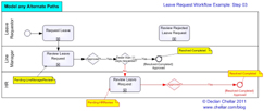
In Step 2 we continued our workflow by using connector shapes to show the flow between the different stages of the work. In this step we are going to model any alternate flows that still lead to an approved leave request (in this case, just one alternate flow).
The business rule we documented in Step 2 told us that in some circumstances, a leave request requires further approval from the HR Department. We now include that alternate path in our diagram, making sure we model any Gateways which would identify further alternate or exception paths.
In the diagram below, anything I have added in Step 3 appears in red.
Some words on statuses: I have placed notes in yellow whenever the status of the work changes. This tells us the status of the work after the previous Activity/Sub-process in the flow and before anything happens in the next Activity/Sub-process.
Keep it short and pithy. A verbose status shows a lack of focus and might not even fit into the field assigned to display it (this is where knowledge of the development tool set gives the analyst some insight into design constraints).
In my opinion it is more useful for the status to indicate what needs to happen next rather than what has just happened (indeed, that is the approach Pegasystems takes with PRPC). In my example, I borrow the PRPC style and use “Pending-” for work that is incomplete and “Resolved-” for work that has reached the end of its flow.
We can infer that there will be exception paths for the scenarios where either the Line Manager or the HR Department does not approve the leave request. We shall model those paths in Step 4.
If you want to see only the posts in this series, select the category “Drawing Workflows“.

Leave a Reply