In Step 1 we started drawing our workflow based on what we knew from the high level statements of requirement in the project scope.
The next step is to start connecting the dots, the dots being the functionality available to the users.
As I said in another post, we can probably produce a reasonably accurate Step 2 based on our prior experience with workflows and have the customer correct us. Alternatively, we can ask the customer to walk us through it.
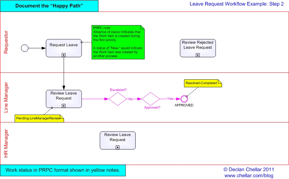
In this step, we connect our Use Cases to start showing the “Happy Path” of the flow of work. We need the following new shapes:
- Connector to show assignment to show flow of work to another person or team (solid line)
- Gateways to show where any alternate and exception paths branch off the Happy Path
- A terminator to show where the Happy Path ends
Gateways in BPMN do not perform any processing, they are simply a visual device for routing the flow. They often relate to business rules. In this case, there is a business rule that for leave requests of 10 days or fewer, the approval of the requestor’s Line Manager is sufficient, but in the case of 11 days or more, further approval from the HR Department is required.
However, Gateways are not always about business rules. For example, a Gateway could simply be used for routing the flow based on some decision an Actor took in the previous Activity or Sub-process.
A note on style: I am trying to use BPMN 2.0 standards to model this workflow, but I would recommend moving to BPMN.
In the diagram below, anything I have added in Step 2 appears in red.
Click on the image to see a larger version
If you have to implement this diagram in a BPM tool such as Pegasystems’ PRPC, notice that I have added a note in yellow to indicate any change in work status.
In Step 3, we will any alternate flows that still lead to an approved leave request.
If you want to see only the posts in this series, select the category “Drawing Workflows“.
Hi Declan,
Great tips on your website. The little things, like highlighting paths which need to be revisited to capture business rules, make so much sense. I can see how this would both keep the drawings organised and the analysis on track so things don’t get overlooked. Looking forward to reading through the rest of your posts.
Take care,
Catherine
Thank you, Catherine. It’s great to hear from you.
Make sure you send me feedback if you use this technique and especially if you adapt it to your needs. This particular style of drawing workflows did not just leap out of my head. Rather it evolved in response to the needs of the various consumers and it will continue to evolve, particularly in the light of Pegasystems’ DCO approach.
Not only that, other analysts have suggested improvements. Remember that it was your colleague, Kiran, who suggested noting on the connectors how the next assignee would get the work.
Spread the word and send feedback. The more people learn from me, the more I learn from them! 🙂