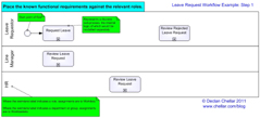
In the foreword, I suggested a definition of “workflow” and provided some high level statements of requirement which provided the scope of our leave request workflow. I also said that four of those statements could be investigated in the form of sub-processes, use cases or user stories. I have tried to comply to BPMN 2.0 standards in my example, so I in my workflow diagram those functional requirements are represented as sub-processes, but as I don’t go into their inner workings in this series of posts, it doesn’t really matter.
The first thing we do is take what we know from the high level statements of requirement and convert them into a visual model.
For our workflow, we will need a swimlane shape to represent each of the three roles mentioned and a use case shape (or a user story shape) to represent each of the four statements of functional requirement. For the moment, we will not show any kind of flow because we do not yet have that information.
If you have to implement this diagram in a BPM tool such as Pegasystems’ PRPC, you should note that where a swimlane is labelled with the name of a specific role, then the work is assigned to Worklist, but where it is labelled with the name of a group, team or department, the work should be assigned to the relevant Workbasket.
In Step 2, we will glean more details from our fictitious customer so that we can start to see the flow itself.
If you want to see only the posts in this series, select the category “Drawing Workflows“.

Leave a Reply